The following information describes how to mount the pulley wheels and fusible link as part of the FEL Free Fall Fire Valve installation within a typical generator enclosure.
Points to consider before commencing installation:
Determine the position of the Fire Valve within the fuel pipework system.
Determine the position of the fusible link over the engine or alternator.
Consider the height of the installed catenary wire when adjacent to or crossing access points or walkways.
Determine the position of the catenary wire anchor point.
Installation:
1. Once you have planned the position of the Fire Valve within the fuel pipework system, measure the offset from the valve centre line to the hole in the valve lever under normal running conditions.
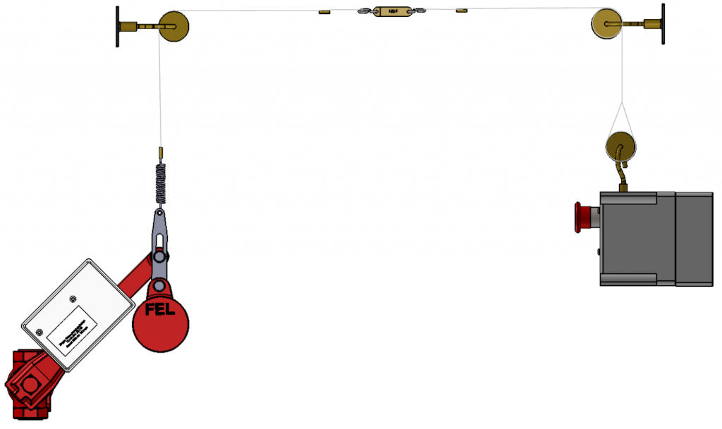
The stainless catenary wire will need to be run vertically upwards from the extension spring which needs to be fitted to the slider inertia bracket at the end of the valve lever.
2. Determine the position of the fusible link, ideally this should be positioned approximately 0.8m-1.0m above the engine/alternator or at the highest possible point should clearance between the generator and the enclosure roof be less than 1 metre.
Make sure the fusible link will be shielded from radiant heat from the exhaust and turbos. Use the S Hooks provided to terminate the catenary wire each side of the fusible link. This will prevent the need to replace the catenary wire should the fusible link need to be changed.
3. To change direction of the stainless catenary wire from vertical to horizontal, install a pulley wheel assembly at the same height as the fusible link.
FEL pulley wheel backplates have been designed to easily fix on to the perforated steel lining often found within generator enclosures, or, you can fix directly to a rail support system using an M6 Rail Nut.
4. Pulley alignment is important to ensure smooth running of the cable when the valve is released. Try to mount the pulley wheel assembly in a position as near to vertical above the fire valve lever/spring, then run the catenary wire as near to horizontal as possible across the engine.
5. Fix the Cable Anchor to the enclosure wall on the opposite side to the Fire Valve location at the same height as the fusible link.
6.Run the Cable with the Fusible Link and S Hooks from the Anchor across the Generator to the wall mounted pulley wheel sited directly above the Fire Valve Lever.
7. The cable must be able to run freely through the Pulley Wheel Assembly. The distance from the Fusible Link S Hook to the Pulley Wheel Assembly must be greater than 750mm to prevent the S Hook from hitting the Pulley Wheel and preventing closure of the Fire Valve.
8. Remember to fix the Warning Sign above any adjacent walkways next to the Generator for safety so that the cable is visible to others.
9. Fix the Fire Valve Lever to the Fire Valve, then fix the Slider Inertia Bracket Link to the Fire Valve Lever, finally, fit the Tension Spring to the tapered end of the Slider.
10. Ensure the catenary wire is sitting within the pulley wheel groove and lift the Fire Valve Lever and determine the length of cable required to hold the lever in the raised position.
11. Fix the cable to the other end of the tension spring using brass ferrules provided. The tension spring should be installed extended by approximately 50mm, this will take up any stretch in the cable which may occur over a period.
12. With the Fire Valve Lever now help in the up position, fix the weight to the opposite end of the Slider using the fixing provided.
13. Test the Fire Valve Assembly so that the valve closes freely, we would always advocate using a Manual or Electro-Manual Quick Release Mechanism to achieve this.
14. Finally, fix the FEL Maintenance Record Card to the Fire Valve with the cable tie provided.
This type of Fire Valve requires regular maintenance, and the record card shows when the valve was installed, as well as when the valve was last maintained.
CALL US NOW ON 01565 733137 OR EMAIL sales@felvalves.com